Processing + OpenCV + Android IPcam : Detect Face

OpenCV + Processing + Android IPcam : Detect Face

All you need for this project is listed below:
1- Processing 3.3.6
2- openCV library for processing + IP-capture library
3- Ipcam App installed on your android device

Specialty of this project is phone camera is used for live camera detection. So you don't need web-cam for this.
Giving you short brief about the need of this project. 

1- Processing 3.3.6
Processing is an open source computer programming language and integrated development environment (IDE) built for the electronic arts, new media art, and visual design communities with the purpose of teaching the fundamentals of computer programming in a visual context, and to serve as the foundation for electronic sketchbooks.


2- Libraries
  • OpenCV
OpenCV (Open Source Computer Vision) is a library of programming functions mainly aimed at real-time computer vision. Originally developed by Intel, it was later supported by Willow Garage and is now maintained by Itseez. The library is cross-platform and free for use under the open-source BSD license.

OpenCV library can be downloaded from the software itself following
Sketch > Import Library > Add library > openCV Processing
{or}
You can download it from github
  1. Unzip it and paste it to Sketchbook>libraries.
  2. To find Sketchbook Location go to File>preferences>browse location.
  3. After successful installation of library you can find example under "Contributed Libraries."

  • IP Capture Library
Similarly you can download IP_Capture library from Sketch > Import Library > Add library
or you can download from Github

3- Ipcam App installed on your android device

There are many ipcam apps are available in playstore but i recommend this one.


After installing all software, libraries, apps lets get started. If you have some issue regarding installing mention in the comment box.

Procedure
  • First  turn on your  phone WiFi Hotspot and connect your PC to it. It will create a Local Network through which both devices can communicate. If you already have private network,then you can connect both your devices to that network
  • Open the IPcam app then go to the bottom and click on Start server. You will see Ip address to get camera stream like "http://192.168.43.1:8080 " note it down.
  • Now open processing and write the following code. It is bit different code than the code given in the OpenCV Contributed examples.
CODE:
import ipcapture.*;
import gab.opencv.*;
import java.awt.Rectangle;
OpenCV opencv;
Rectangle[] faces;

IPCapture video;
PImage src; //separate image variable to capture from Ip cam

void setup() {
  size(640,480); // can use full screen instead
  //fullScreen();
  video = new IPCapture(this);
  video.start("http://192.168.43.1:8080/video"," "," ");
}
void opncv() // function openCV
{
  opencv = new OpenCV(this, src);
  opencv.loadCascade(OpenCV.CASCADE_FRONTALFACE);
  // See library reference to Detect eye,body,nose etc.
  faces = opencv.detect(); 
}
void getlive() {
    if (video.isAvailable()) 
    {
    video.read();
    }
    image(video,0,0); // draw image on screen
    src = get();
    // get what is drawn on screen and paste that to src image
    clear();
  }

void draw() {
  getlive(); //get live image
  opncv();
  image(src, 0, 0);// show live image on screen
  noFill(); // show a rectangle around face
  stroke(0, 255, 0);
  strokeWeight(3);
  for (int i = 0; i < faces.length; i++) {
    rect(faces[i].x, faces[i].y, faces[i].width, faces[i].height);   
  }
}
  • This is the result you will get.


Thanks for visiting my blog.
If you face some issue comment.

LINE FOLLOWER Part 4 :Coding and Run

LINE FOLLOWER Part 4 :Coding and Run

Coming to the final blog of Line Follower I have given the code for this,Copy this and directly paste it in Arduino IDE and modify according your needs.
Code is for only 3 sensor input and its good for Beginners.
Here's the Code:
_________________________________________________________________________________
//Code is for 3 sensor input//code by-Https://ganeshgadgets.blogspot.com

int ena = 11;//a-LEFT motor PWM output  
int enb = 10;//b-RIGHT motor PWM output
int ar = 12;//a reverse//
int af = 13;// aforward//
int bf = 9;//b forward//
int br = 8;//b reverse//

int s1 = 14, s2 =15, s3 =16; //3 sensors connected to analog a0,a1,a2 pins(digital equivalent)

void setup() {
  // put your setup code here, to run once:
  // declaring output pins
  pinMode(ena,OUTPUT);// declaring output pins
  pinMode(enb,OUTPUT);
  pinMode(ar,OUTPUT);
  pinMode(af,OUTPUT);
  pinMode(bf,OUTPUT);
  pinMode(br,OUTPUT);
  // declaring input pins
  pinMode(s1,INPUT);
  pinMode(s2,INPUT);
  pinMode(s3,INPUT);
  }

void loop() {
  // put your main code here, to run repeatedly:
  //case-1 FORWARD 
  if((digitalRead(s1)==HIGH) && (digitalRead(s2)==LOW) && (digitalRead(s3)==HIGH))
  {
  digitalWrite(ena, HIGH);// BOTH ENABLE PIN WILL BE HIGH FOR ALL CASES
  digitalWrite(enb, HIGH);

  digitalWrite(af, HIGH);
  digitalWrite(ar, LOW);
  digitalWrite(bf, HIGH);
  digitalWrite(br, LOW);
  }
  //case-2 SMOOTH TURN RIGHT  
  if((digitalRead(s1)==HIGH) && (digitalRead(s2)==HIGH) && (digitalRead(s3)==LOW))
  {
  digitalWrite(ena, HIGH);
  digitalWrite(enb, HIGH);

  digitalWrite(af, HIGH);
  digitalWrite(ar, LOW);
  digitalWrite(bf, HIGH);// GIVING BOTH HIGH RESULTS IN STOPPING RIGHT MOTOR
  digitalWrite(br, HIGH);
  }
  //case-3 SMOOTH TURN LEFT   
  if((digitalRead(s1)==LOW) && (digitalRead(s2)==HIGH) && (digitalRead(s3)==HIGH))
  {
  digitalWrite(ena, HIGH);
  digitalWrite(enb, HIGH);

  digitalWrite(af, HIGH);// GIVING BOTH HIGH RESULTS IN STOPPING LEFT MOTOR 
  digitalWrite(ar, HIGH);
  digitalWrite(bf, HIGH);
  digitalWrite(br, LOW);
  }
  //case-4 STOP OR START
  if((digitalRead(s1)==HIGH) && (digitalRead(s2)==HIGH) && (digitalRead(s3)==HIGH))
  {
  digitalWrite(ena, HIGH);
  digitalWrite(enb, HIGH);

  digitalWrite(af, HIGH);// GIVING ALL HIGH BOTH MOTORS WILL BE STOPPED
  digitalWrite(ar, HIGH);
  digitalWrite(bf, HIGH);
  digitalWrite(br, HIGH);
  }
  //case-5 STOP OR START
  if((digitalRead(s1)==LOW) && (digitalRead(s2)==LOW) && (digitalRead(s3)==LOW))
  {
  digitalWrite(ena, HIGH);
  digitalWrite(enb, HIGH);

  digitalWrite(af, HIGH);// GIVING ALL HIGH BOTH MOTORS WILL BE STOPPED
  digitalWrite(ar, HIGH);
  digitalWrite(bf, HIGH);
  digitalWrite(br, HIGH);
  }
  //case-6 SHARP RIGHT TURN
  if((digitalRead(s1)==HIGH) && (digitalRead(s2)==LOW) && (digitalRead(s3)==LOW))
  {
  digitalWrite(ena, HIGH);
  digitalWrite(enb, HIGH);

  digitalWrite(af, HIGH);
  digitalWrite(ar, LOW);
  digitalWrite(bf, LOW);// THIS WILL REVERSE MOTOR B
  digitalWrite(br, HIGH);
  }
  //case-7 SHARP LEFT TURN 
  if((digitalRead(s1)==LOW) && (digitalRead(s2)==LOW) && (digitalRead(s3)==HIGH))
  {
  digitalWrite(ena, HIGH);
  digitalWrite(enb, HIGH);

  digitalWrite(af, LOW);// THIS WILL REVERSE MOTOR A
  digitalWrite(ar, HIGH);
  digitalWrite(bf, HIGH);
  digitalWrite(br, LOW);
  }
  //case-8 ANTINODE DETECT 
  if((digitalRead(s1)==LOW) && (digitalRead(s2)==HIGH) && (digitalRead(s3)==LOW))
  {
  digitalWrite(ena, HIGH);
  digitalWrite(enb, HIGH);

  digitalWrite(af, HIGH);//IGNORING ANTINODE CONDITION AND MOVING FORWARD
  digitalWrite(ar, LOW);
  digitalWrite(bf, HIGH);
  digitalWrite(br, LOW);
  }
}
_________________________________________________________________________________

  • You can use more sensors in If Statement like;
 if((digitalRead(s1)==HIGH) && (digitalRead(s2)==LOW) && (digitalRead(s3)==HIGH) && (digitalRead(s4)==HIGH) && (digitalRead(s5)==HIGH) && (digitalRead(s6)==HIGH))
{........}

  • You can add speed variation in :
  analogWrite(ena, 200);//0-255
  analogWrite(enb, 200);//0-255

This is end of line follower project. For more tech and projects follow me.


LINE FOLLOWER Part 3 : CONNECTING ALL TOGETHER AND CONCEPT

LINE FOLLOWER Part 3 : CONNECTING ALL TOGETHER AND CONCEPT

Coming to the part 3 all you need is- 
  1. Arduino UNO(you can use others also,but I prefer UNO for beginners)
  2. Sensor Array(min 3 to max 5 numbers of ir sensors)
  3. Motor Driver(L298 or any other)
  4. Line follower Chassis
  5. Two DC motors
  6. Jumper Wires(male-female,female-female)
  7. Wheels and an Castro Wheel(Multi directional wheel)

Connect all the Modules According to the diagram given below:-


Points Worth Noting:-
  • All the modules should have a common ground. Every time you add any module to your project you should add ground of module to the ground pin of Arduino.
  • Connect the enable of motor Driver to any of PWM pins(3,5,6,9,10,11). It will help you to control the speed of Motor.
  • If you don't want speed Control then add enable pin to 5V of motor Driver or Vin, it will then take max speed in default.
  • Put all your sensor input to the analog pins. Its more convenient and gracious. You can use these pins as analog(A0....A5) or as digital pins(14-19). Digital input is better for line follower.
Concept Behind the Line follower Algorithm:
I will discuss the concept or the idea that can you use easily. Suppose you have 3 sensors so there are total of 8 possibilities of sensor values.
You can use the formula-2^(No. of sensors)"
If you are using 5 sensors then you have 2^5=32 possibilities.
Lets go in detail....
See the figure

  • The sensor give digital HIGH while on white surface and digital LOW on black surface or VICE VERSA if you have sensor of inverting mode(op-amp).
  • Here we are considering following black line on white surface.
  • Going case by case.
CASE
ACTION REQUIRED
LEFT MOTOR
RIGHT MOTOR
1
FORWARD
FORWARD
FORWARD
2
SMOOTH TURN RIGHT  
FORWARD
STOP
3
SMOOTH TURN LEFT  
STOP
FORWARD
4
STOP OR START
STOP OR FORWARD
STOP OR FORWARD
5
STOP OR START
STOP OR FORWARD
STOP OR FORWARD
6
SHARP RIGHT TURN
FORWARD
REVERSE
7
SHARP LEFT TURN
REVERSE
FORWARD
8
ANTINODE DETECT
STOP OR FORWARD
STOP OR FORWARD


  • For simplicity here speed control is not disscussed. You can do that using Enable pin and analogWrite(pin number, 0-255) in arduino codes.
  • Codes to the line follower bot is in next blog.


LINE FOLLOWER PART 2: MOTOR DRIVER

LINE FOLLOWER PART 2: MOTOR DRIVER

Coming to the second part of our discussion and thats the motor driver. So the motor driver is basically an electronic circuit that drives/control the motor by controlling the voltage across the terminal. It can move the motor(DC motors) back and forth with a variable speed range.

TYPES OF MOTOR DRIVER

1. L293D BASED
* It is cheaper,lesser components, does not require a heat sink.
Description
* 600mA OUTPUT CURRENT CAPABILITY PER CHANNEL
* 1.2A PEAK OUTPUT CURRENT (non repetitive) PER
* CHANNEL ENABLE FACILITY
* OVER TEMPERATURE PROTECTION
* LOGICAL "0" INPUT VOLTAGE UP TO 1.5 V (HIGH NOISE IMMUNITY)


2.L298D BASED  
* Its comparatively costlier,needs heat sink, more current carrying capacity.
Description
The LN298 is a high voltage, high current, dual full-bridge motor driver designed to accept standard TTL logic levels and drive inductive loads such as relays, solenoids, DC and stepping motors.
- Operating supply voltage of up to 46V
- 4.5-7VDC logic supply voltage
- Total DC current of up to 4A
- Over-temperature protection
                                                      - Logical ‘0’ input up to 1.5V (high-noise immunity)
PINS LAYOUT IN MOTOR DRIVERS
Power pins- through which power is feeded in. These are VCC+ and GND- . 12V input is given to it.
Motor outputs pins- outputs to the motors are given through this.
ENA, ENB(enable A,B) - It works as enable to circuit and also speed control for the motors. It regulates the voltage from 0-12V with logical signal of 0-5V input from arduino.
Pins A1,A2 and B1,B2- these and used for controlling the direction of the motor.
A1
A2
ACTION
LOW
LOW
NO ACTION
LOW
HIGH
FORWARD
HIGH
LOW
BACKWARD
HIGH
HIGH
STOP

Similar action can be used for motor B.

CHOICE OF MOTOR
BO MOTOR STRAIGHT
BO MOTOR L-SHAPED
Centre shaft DC geared motor or plastic motor (B.O.motor) works fine with line follower.
 THANK YOU FOR READING THE BLOG.....

LINE FOLLOWER: PART 1 - IR SENSORS

The line follower can be divided into 3 subparts.
They are-
1. Sensors
2. Motor and Driver
3. Microcontroller
In this blog only sensors will be discussed.

LINE FOLLOWER: PART 1 - IR SENSORS

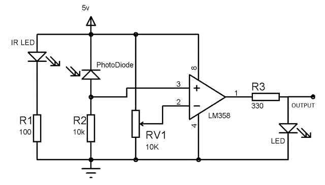
Sensor is like an eye for line following robot and through this digital signal is fed to the arduino.
Sensor are of two kinds-
1. Analog (gives signal between the value 0-1023 for 0-5V input)
2. Digital (gives signal of either 0 or 1)

Digital sensors are prefered because of better sensitivity and lesser programming. The components of digital sensors are
1. IR Sender and Receiver
2. LM358 IC 2 IR transmitter and receiver pair
3. Resistors of the range of kilo ohms
4. Variable resistors.
5. LED (Light Emitting Diode).
6. PCBs and soldering Equipments 

WORKING PRINCIPLE
When the ir rays from ir sender are reflected from the object and fall on the IR receiver, it changes its state of open to close, behaving as a switch.
It offers minimum resistance when ir rays fall on it.


JOB OF LM358 IC

The abbreviation LM358 indicates an 8-pin integrated circuit, comprising two operational amplifiers at low power. The LM358 is designed for general use as amplifiers, high-pass filters, low band pass filters, and analog adders.

It is used as a comparator here. It compares between the reference 
voltage with the signal from the ir receiver, if signal is greater than reference then out put will be 1 or digital HIGH. else it will be 0 or digital LOW.

CIRCUIT FOR SENSOR MODULE
If you are interested of building one sensor at your own. but its better to buy these.
MODULES YOU BUY ONLINE
These can be of one sensor or sensor array
SINGLE SENSOR MODULE
MULTI SENSOR MODULE


It's better to use multiple sensors for better accuracy. You will atleast need 2 single sensor for operation. SIX sensor are better if you are using arduino UNO,you can connect them in analog pins.
If you are using MEGA no pin nos is concerned.

The distance sensing capability can be adjusted by using the potentiometer spinning it in appropriate direction.Any sensor module must have a VCC+ and GND- pin with them and output pins of equal numbers of sensors. 5V supply to the sensor is quite good for the operation. If you are using separate source for sensor you should make the ground common with arduino's ground.

Thanks for reading my blog........


How to burnt Arduino and repaired it.

It is quite harsh and sad if your arduino stops working. It a heart breaking experience because it's your project's heart. I am discussing how one can burnt arduino.
Can it be repairable !!! Yes or No?? and if yes HOW!!!


How to break/burn/damage Arduino.

1. Overvoltage 

Though arduino have voltage regulator it works between 5-20V and 7-12 V be the desirable ones. Giving more than that is risky.

2. Shorting Input/output pins or overvoltage them.

     I was once working with a motor driver circuit and one of 12v terminal got connected with input and that damage the AtMega328 IC. Later I was able to replace that one and made my arduino work again.From my experience I suggest that you never short you input or put high volts through them.

3. Unwanted connections

     Recently I damaged my arduino by an unconventional way that is unrepairable. I had a open wire of 12v that came contact with 6pins of FDTI (don't know particular).So this result in damaging the FDTI permanently and the arduino board is shorted. Atmega chip was damaged and when I tried replacing it with another chip....I lost both of them. I have no idea how to repair.

4. Over load operations 

     Another case its not damaged actually,it happen when u tried to switch on and after working a bit it stop suddenly. It may be the supply isn't up to the demand of load connected to arduino. This can be resolved using power source having more ampere power.

So up above are the cases one can damage arduino. Now its repairing time.
Make sure if it is repairable...
First remove the atmega chip from board. For nano,mega and other non removable chip users...RIP...
For UNO users remove it. Then plug it up and see if the led of rx/tx and pin-13 blink once or more. If yes then your board is healthy. Replace the Atmega chip with new one with arduino UNO bootloader. It is available in online shopping sites. Most of the Atmega 328 used in arduino comes with uno bootloader. If you can't get a chip I can help you in later blog if I have any requests.
If the leds don't blink, or stays on..your board is damaged... RIP...
Hope You liked it. Like my blog.
"Never lose hope when you fail, those who don't fail haven't tried anything new."
    

Portable emergency mobile charger

Portable emergency mobile charger

KISS is a better way to build things. I mean Keep It Simple Stupid(KISS). In this post I will build a simple Mobile charger using a DC geared motor.

Things you needed:

1. DC geared motor(100 or 150 rpm)
2. 5V voltage regulator(7805 IC)
3. USB female connector


Tools: soldering things, hot glue gun, wires, plastic case


CIRCUIT DIAGRAM:


When the shaft of dc motor is rotated at suitable speed it generate about 5-12 V. The voltage regulator here works as constant voltage source to mobile device as mobile and many other electronic devices run at contant 5V DC. So any unwanted higher value is cut off by 7805 IC.

SO MAKE IT HAPPEN....

1. make the connections
2. make place for the motor
3. make place for usb_female and stick it with hot glue.

4. build a handle for rotating the shaft
5. Finally bring all together and test if your phone charges.

Thank you for reading this blog. Hope you have enjoyed it.