The line follower can be divided into 3 subparts.
They are-
1. Sensors
2. Motor and Driver
3. Microcontroller
In this blog only sensors will be discussed.
LINE FOLLOWER: PART 1 - IR SENSORS
Sensor is like an eye for line following robot and through this digital signal is fed to the arduino.
It's better to use multiple sensors for better accuracy. You will atleast need 2 single sensor for operation. SIX sensor are better if you are using arduino UNO,you can connect them in analog pins.
If you are using MEGA no pin nos is concerned.
The distance sensing capability can be adjusted by using the potentiometer spinning it in appropriate direction.Any sensor module must have a VCC+ and GND- pin with them and output pins of equal numbers of sensors. 5V supply to the sensor is quite good for the operation. If you are using separate source for sensor you should make the ground common with arduino's ground.
Thanks for reading my blog........
They are-
1. Sensors
2. Motor and Driver
3. Microcontroller
In this blog only sensors will be discussed.
LINE FOLLOWER: PART 1 - IR SENSORS
Sensor is like an eye for line following robot and through this digital signal is fed to the arduino.
Sensor are of two kinds-
1. Analog (gives signal between the value 0-1023 for 0-5V input)
2. Digital (gives signal of either 0 or 1)
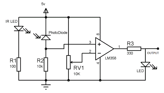
Digital sensors are prefered because of better sensitivity and lesser programming. The components of digital sensors are
1. IR Sender and Receiver
2. LM358 IC 2 IR transmitter and receiver pair
3. Resistors of the range of kilo ohms
4. Variable resistors.
5. LED (Light Emitting Diode).
6. PCBs and soldering Equipments
WORKING PRINCIPLE
1. IR Sender and Receiver
2. LM358 IC 2 IR transmitter and receiver pair
3. Resistors of the range of kilo ohms
4. Variable resistors.
5. LED (Light Emitting Diode).
6. PCBs and soldering Equipments
WORKING PRINCIPLE
When the ir rays from ir sender are reflected from the object and fall on the IR receiver, it changes its state of open to close, behaving as a switch.
It offers minimum resistance when ir rays fall on it.
JOB OF LM358 IC
 The abbreviation LM358 indicates an 8-pin integrated circuit, comprising two operational amplifiers at low power. The LM358 is designed for general use as amplifiers, high-pass filters, low band pass filters, and analog adders.
It is used as a comparator here. It compares between the reference
voltage with the signal from the ir receiver, if signal is greater than reference then out put will be 1 or digital HIGH. else it will be 0 or digital LOW.
CIRCUIT FOR SENSOR MODULE
If you are interested of building one sensor at your own. but its better to buy these.
MODULES YOU BUY ONLINE
These can be of one sensor or sensor array
 |
| SINGLE SENSOR MODULE |
 |
| MULTI SENSOR MODULE |
It's better to use multiple sensors for better accuracy. You will atleast need 2 single sensor for operation. SIX sensor are better if you are using arduino UNO,you can connect them in analog pins.
If you are using MEGA no pin nos is concerned.
The distance sensing capability can be adjusted by using the potentiometer spinning it in appropriate direction.Any sensor module must have a VCC+ and GND- pin with them and output pins of equal numbers of sensors. 5V supply to the sensor is quite good for the operation. If you are using separate source for sensor you should make the ground common with arduino's ground.
Thanks for reading my blog........


No comments:
Post a Comment